I was hooked. I ordered one right then and there. I was told the kits would ship in a few weeks and that they wouldn't charge my card until the kit went out! Eight long weeks later, my kit finally arrived. Rubicon Express picked up the shipping bill since the kit had been delayed. I inventoried the kit and called Rubicon Express with a few minor questions. I told them I was doing the install the next day (Saturday). Since the shop was going to be closed, one of Rubicon Express' owners actually gave me his home number to call him if we had any questions. I don't ever recall any manufacturer offering this service to me before.
The kit included the following parts
(everything below except the saw blades, lubricant, and Loktite):
| 4 coil springs - 10% higher spring rate |
| 4 lower control arms - Heim joint/rod end on axle end, bushing on frame end - requires removal of one end to adjust length |
| 2 front upper control arms - bracket/rod end on axle end, Heim joint/rod end on frame end - length adjustable by turning the center of the rod like a drag link |
| 2 rear upper control arms - Heim joint/rod end at both ends - length adjustable by turning the center of the rod like a drag link |
| 2 front sway bar links - two pin style with removable center section |
| 2 extended rear sway bar links |
| 1 front adjustable track bar - allows centering of axle under vehicle and eliminates need for dropped Pitman arm |
| 1 rear track bar relocating bracket - allows centering of axle using existing track bar |
| 2 stainless steel front brake lines and brackets |
| 1 NVG 231 slip yoke eliminator kit - fixed yoke, tap, and drill |
| 1 rear drive shaft - includes greaseable Spicer u-joints at both ends and new u-joint straps |
| 2 Front bump stops pucks - mount on the lower spring perch |
| 2 rear bump stop extenders - mount between frame and factory bump stop cup |
| 4 DoetschTech DT-3000 shocks |
| Assorted fasteners, including L9 grade fasteners which are stronger in shear and tension than Grade 5 and 8 |
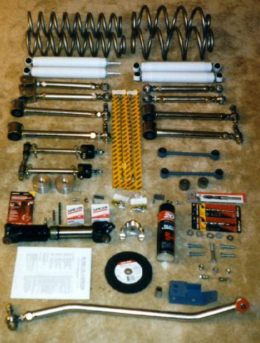
| 9/16" drill bit - to enlarge holes for stronger hardware |
| 7" metal cutting circular saw blades - to cut transfer case shaft |
| Silicone spray - to make pushing bar pins and sleeves in shock bushings easier |
| Loktite 271 Red - to augment self locking hardware |
I used the following tools:
| Common hand tools |
| Electric drill |
| Circular saw |
| Vise |
| Air wrench and ratchet - not required, but helpful |
| Torque wrench |
| Spring compressors - not required, but helpful |
| Professional garage frame lift - $4.75/hour at the Andrews AFB Auto Hobby Shop |
| Transmission jack - to support axle |
Here are the steps we followed. These differ slightly from the instructions RE included with the kit. This was done to make some steps a bit easier. The items in red are inputs from Wayne Bennett at 4X4NOW and Paul Davidson. They have installed the RE 4.5" systems in their TJs too.
| 1. Raise vehicle and support with stands. |
| 2. Remove wheels. |
| 3. Remove front shocks. |
| 4. Remove front sway bar end links. Use a hammer against the end of the sway bar while pulling down on the link to get the old links to release. |
| 5. Remove front spring retainer clamp on driver's side. |
| 6. Remove front springs. Spring compressors may be helpful. Pull the bump stops off to gain additional clearance to remove springs. |
| 7. Support the front axle with jack stands. |
| 8. Remove front upper and lower control arms. If you are using jacks and jack stands, you might find it easier to do the lowers first, then the uppers rather than both at the same time. The lower arms have a caster adjuster on them which you will re-use. The early production kits came with heavier L9 hardware, so the caster cam could not be re-used. The upper arms use self holding nuts, so you only need one wrench to remove them. |
| 9. Remove factory brake lines and replace with supplied lines. |

| 10. Drill 5/16" hole in center of lower spring pads. |
| 11. Use self-tapping bolt through the bumpstop extension to cut threads in lower spring pad. Remove bolt and spacer, it will be re-installed with the spring. |
| 12. Drill front lower control arm mounts at the axle to 9/16", to accommodate the L9 (gold colored) replacement hardware. This step is not necessary if you plan to re-use the adjuster cam. |
| 13. Install the lower control arms with the rubber bushing at the frame mount. Set the length to 1/4" longer than stock. The heim joint goes forward. Torque to 130 ft-lbs at both ends if using the L9 hardware. If using the adjuster cam, torque to 85 ft-lbs. The offset goes inboard for extra tire clearance. The wider spacer goes outboard and the narrower spacer goes inboard. Use the factory bolt and nut at the frame mount, and the supplied L9 (gold colored) hardware at the axle mount. |
| 14. Install the upper control arms. Set the length to 1/8" longer than stock. Torque to 55 ft-lbs. Re-use the factory hardware. The forked end goes forward, the heim joint to the rear. You may need to buy some slightly longer bolts for the axle end of the control arm. |
| 15. Install the front springs with the bumpstop extension inside of the coil. Coil spring compressors may be useful. If you don't have spring compressors, you can get a little extra clearance by disconnecting one end of the track bar. Once the spring is in place, thread the bolt into the lower spring pad. Rotate the coil to index the pigtail end of the spring with the indent in the lower spring pad. The indent is hidden on the passenger side spring. |
| 16. Install the spring clamp you removed earlier. Driver's side only. You can get a clamp and screw for the passenger's side at the dealer. |
| 17. Install the supplied bar pins through the bottom shock eyes and install shocks. The easiest method was to use a vise and a large set of pliers. Place the shock in the vise with the rubber bushing on one side and the bar pin on the other. Begin closing the vise. Use the pliers to squeeze the bushing into an oval shape to allow the bar pin to pass through the bushing. A little silicone spray lube helps as well. |
| 18. Remove old track bar assembly. |
| 19. Use 9/16" drill bit to drill track bar upper mount at frame. |
| 20. Drill 1/2" hole in lower mounting location, and use the supplied 1/2" bolt to mount track bar. |
| 21. Tighten lower mounting bolt to 55 ft-lbs. Leave the top end loose. You will adjust it later. |
| 22. Install sway bar disconnect adapter bracket by inserting stud on top of adapter through ring on end of sway bar. Use the large USS washer and nut on top of adapter bracket to secure adapter bracket to sway bar. |

| 23. Install reducer sleeve in end link urethane bushing. |
| 24. Attach end link to adapter bracket with supplied bolt. |
| 25. Attach end link to mount on axle with supplied bolt, using spacer to maintain proper offset. |
| 26. Remove the rear shocks. |
| 27. Remove the rear sway bar end links. |
| 28. Support the rear axle. |
| 29. Remove the lower and upper rear control arms. If you are using jacks and jack stands, you might find it easier to do the lowers first, then the uppers rather than both at the same time. The upper arms use self holding nuts, so you only need one wrench to remove them. You may want to release the muffler brackets to allow better access to the passenger side, forward, upper control arm bolt. Once the muffler is lowered, you can use a long extension on your ratchet to remove the bolt. |
| 30. Remove the rear springs. Pull the bump stops off to gain additional clearance to remove springs. |
| 31. Remove the plastic dust shield that covers the bolt securing the rear track bar to the mount on the axle housing and discard. |
| 32. Remove the Torx head bolt (T55) and disconnect axle end of track bar. |
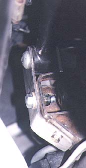
| 33. Install track bar bracket using the supplied 2-3/4" bolt and 1-1/2" spacer sleeve (the spacer sleeve goes in the location vacated by the track bar to prevent the bracket from deforming when the bolt is tightened). Newer kits might have a shorter bolt and no spacer sleeve. |
| 34. With the track bar bracket in place, drill 5/16" holes in the axle mount where the plastic dust shield was previously located. |
| 35. Remove the bolt to allow access for installing the 5/16" hardware in the holes you just drilled. |
| 36. Install the lower control arms with the rubber bushing at the frame. Set the length to minimum. The offset goes outboard. Torque to 130 ft-lbs. Re-use the factory hardware at the frame and the supplied L9 (gold colored) hardware at the axle mount. |
| 37. Install the upper control arms re-using the factory supplied hardware. Set the length to 1/2" longer than stock. Torque to 55 ft-lbs. Re-position the muffler and re-attach the brackets. |
| 38. Remove the rubber insert from the rear bump stop. Remove the bump stop cup. Place the spacer between the bump stop cup and the frame using the supplied longer metric hardware. |
| 39. Install springs. Spring compressors may be helpful. If you don't have spring compressors, you can get a little extra clearance by disconnecting one end of the track bar. |
| 40. Install the track bar in the track bar bracket using the Torx bolt you removed earlier. Torque to 55 ft-lbs. |
| 41. Install replacement sway bar end links. |
| 42. Install rear shocks. Install them body-up for clearance if using the CV shaft. |
| 43. Remove the rear drive shaft. |
| 44. Measure and mark transfer case output shaft so that 1.0" of splined shaft will remain. Put a piece of masking tape around the shaft and mark it. |
| 45. Cut the transfer case output shaft with abrasive cutting wheel. I used a circular saw with a metal cutting blade. It took 20 seconds to cut through. |
| 46. Grind end of shaft square. It just has to be close. |
| 47. Center punch shaft to ensure drill starts in center of shaft. Use a ruler and a scribe to draw a line from top to bottom and side to side. The intersection is the place to use the center punch. |
| 48. Using drill and supplied drill bit, start pilot hole in end of shaft. |
| 49. Next drill hole in center of stock slip yoke. You must remove the old u-joint to do this. The slip yoke will be used as a guide to ensure hole is drilled directly through the bore of 231 shaft. |
| 50. Using stock slip yoke on the end of your 231 shaft, bore hole 1-1/4" deep into 231 shaft. Be patient and use lots of cutting oil. |
| 51. Use the supplied tap to cut threads in end of output shaft. Use oil while cutting threads and keep tap clean. Run the tap in 3 turns then back out 2, keep repeating this cycle, occasionally fully removing the tap to clean and oil it. |
| 52. Install yoke using supplied 5/16"-18 bolt (use Loktite). Heat the yoke in a bucket of very hot water to make it expand. Let the freshly drilled shaft cool at the same time. Use grease and a rubber mallet to help install the yoke. Just get it started and straight, then use the bolt to pull the yoke on the rest of the way. |
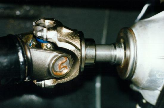
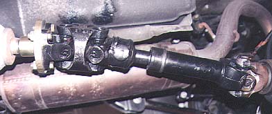
The fixed yoke is now installed.
New kits include a CV style yoke and shaft.
The standard style will look like the picture on the left and the CV style
will look like the picture on the right:
| 53. Install driveshaft using supplied strap kits. You will have 4 bolts to attach at the CV if you have the new kit. |
| 54. Grease u-joints and slip splines in driveshaft. |
| 55. Install tires. |
| 56. Lower the vehicle to the ground. |
| 57. Adjust the front track bar. Center the vehicle over the axle by measuring the distance from front fender flare to tire on both driver and passenger sides of the vehicle, then adjusting vehicle until body is centered over the axle (it may be necessary to have someone push the body to accomplish this). |
| 58. Adjust heim joint so that it will fit directly into the upper mount with the body centered. |
| 59. Tighten the jam nut to prevent the heim joint from moving. |
| 60. Use supplied hardware to attach the heim joint to the factory mount. |
| 61. Tighten the upper mounting bolt and lock nut to 130 ft-lbs. |
| 62. Thoroughly bleed brake lines and check for leaks. |
| 63. Double-check all nuts and bolts. |
| 64. Check fluid levels. |
| 65. Test drive and inspect for leaks. |
| 66. Re-tighten bolts and re-grease driveshaft after first 100 miles. |
| 67. Align vehicle as soon as practical. |
Right after we installed the kit, we found a loading ramp that measured 20 degrees. We ramped 1000+ with the front sway bar still attached (I forgot to pull the disconnect pins). The ride is not harsh and feels about the same as the factory suspension did before I Rhino Lined the tub/rockers, added heavier bumpers and larger spare, and added a Warn XD9000i winch.
Overall, my impression is that this is one outstanding kit...complete, well engineered, and very flexy. Also, I really like the service I received from Rubicon Express. They went above and beyond any other shop I have previously dealt with.
