Enter Rubicon Express. Yes, these are the same guys who build THE best lift system for the TJ. But they also are now in the axle building business...sort of. You see, Ryan at RE wanted to make some really bulletproof brackets that addressed some of the shortfalls of the stock bracketry...weak, no spring retention system, and too short to work with 3"+ lifts without bolt on bracket extensions. So he started designing a completely new set of brackets for aftermarket axles. The end result of his 5 months of labor is a set of brackets that address all the factory shortfalls...they are 50% thicker, there is a simple, yet very effective spring retention system, and there is a built in bracket extension to accommodate big lifts.
Now remember I said they are "sort of" in the axle building business. Truth is, all they do is build the brackets and assemble them to the housing. In fact, anyone can now buy the bracket sets direct from RE or even have another company buy them for use on an aftermarket axle housing. But, RE does not build the bare housing, nor do they load them. RE gets Currie Enterprises to build the housings, and in my case, they had a D60 built to their (my) specifications. This included equal length shafts (the differential is pushed slightly to one side) so a single spare will work on either side. It also includes 11" x 2.75" drum brakes, 4.88 gears, and special machining for an ARB air locker. The finished housing had the brackets welded on at RE's shop and then it went out to have the internals loaded up. By the way, the brackets were welded on with the housing rotated up so the brackets would be properly aligned while the pinion was pointed up for the CV driveshaft. Once this was done, the housing was painted and sent out to me.
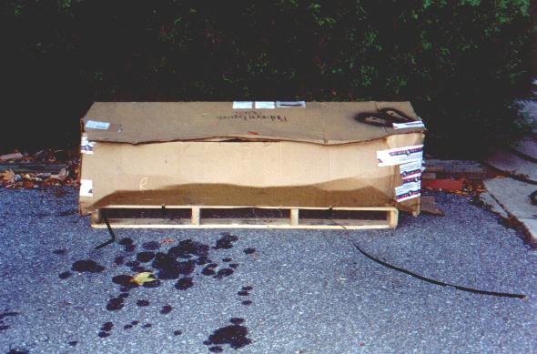
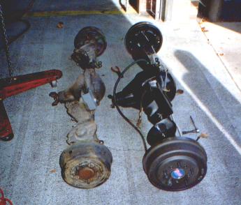
The first shot shows how it looked
when it arrived (I've already cut the box open and cut the straps off).
The second shot shows how it looked when I got the box opened:

Along with the new axles, I had RE supply me with a set of their 2nd generation control arms. These arms eliminate the heim joints that were found on the 1st generation control arms and change the offset to downward, from inward on the originals. While I never personally had any problems with the heim joints (and still feel they are excellent for this application), I liked the look of the new arms, especially the downward offset which allows a bit more droop that the earlier units. The new arms use a 2 piece polymer race surrounding a large spherical joint. The assembly is held together with a large washer on one side (held in by a cir-clip) and a pre-load adjuster on the other side. The setup is similar to the Currie/Tomken "Johnny Joint", but eliminates the noisy urethane races and the slop. The new joints are also cheaper to re-build, if necessary, than the old heims ($25 for a heim vs $8 for a new set of polymer races).
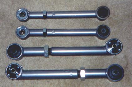
Here's what the new arms look like (the uppers are above and the lowers are below). The large nuts are jam nuts to lock in the length once the pinion angle is properly set:
| 1. Lift the vehicle by the frame and support the old axle with an axle or transmission jack. |
| 2. Remove the bolts securing the upper and lower control arms. I left the frame end upper control arm bolts in as I wanted to leave the upper arms installed to facilitate adjusting the pinion angle (the old style arms are double adjustable like a drag link). |
| 3. Remove the sway bar links. |
| 4. Remove the T-55 Torx bolt securing the rear track bar. |
| 5. Remove the springs. |
| 6. Disconnect the rear brake line at the frame and plug it with a rubber cap. |
| 7. Disconnect the emergency brake cables. This was fairly tricky as I did not want to disassemble the brakes. I was able to remove the small coil spring from the rear shoe and rotate the shoe forward enough to slip the cable end off the brake arm. Once this was done, it was a fairly easy matter to remove the cable from the brake housing. |
| 8. Disconnect the lower shock bolts. |
| 9. Remove the driveshaft. |
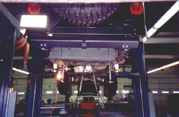
| 10. Lower the axle away from the vehicle. |
| 11. Transfer the brake lines, axle vent line, and sway bar (if desired) from the old axle to the new axle. The brake lines required a few minor re-bends to get it just right. Later, I used 150 pound marine zip ties to secure the brake line to the housing. The vent line was a bit too short now, since the vent is not in the same location on the new axle as the old axle. I did not transfer the sway bar as it doesn't really do much other than limit droop. On stock axle setups, this is necessary to prevent the springs from falling out, but this is not necessary with the new brackets. |
| 12. Raise the new axle up to the vehicle. |
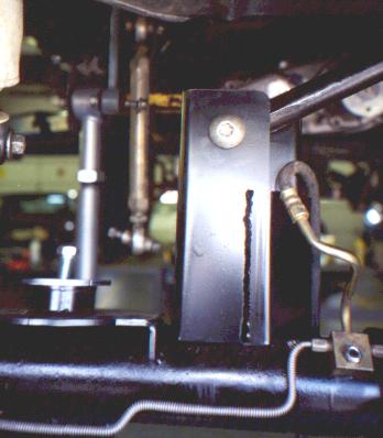
| 13. Connect the rear track bar to the bracket and torque the bolt to 75 ft-lbs. |
| 14. Connect the upper and lower control arms. Torque the lowers to 130 ft-lbs and the uppers to 55 ft-lbs. . |
| 15. Re-install the rear drivehshaft. At this point, I installed the Boggers and cycled the axle up and down to check the tire to body clearance, the shock length, differential cover plate to gas tank clearance, and driveshaft length. The tires barely rub the rear of the fender when the axle is raised on one side only. The amount of rubbing will be easily eliminated with a little trimming once I get the new fender flares. The shocks were just barely too short (by about 1/8"). I might add limiting straps at some point to prevent damage to the shocks. The differential cover plate cleared the gas tank skid plate by a scant 1/8". The drive shaft was too long by about 1/2" and was removed. |
| 16. Connect the shocks and torque to 75 ft-lbs. |
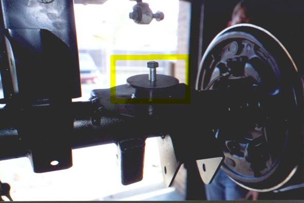
| 17. Install the springs and spring retainers. |
| 18. Since the axles are double drilled for 5 on 4.5" and 5 on 5.5", I pulled the rear axle shafts and reset the studs on 5 on 4.5". This is because I cannot run the Boggers until I get the front axle installed. |
| 19. Reconnect the brake line at the frame connection. |
| 20. Connect the emergency brake cables. I used the same trick again and it worked well. |
| 21. Lower the vehicle and bleed the brakes. |
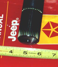
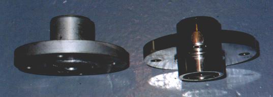
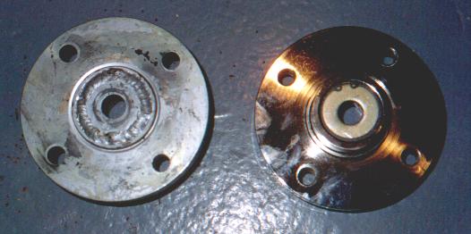
Here are two pictures of the old yoke
and the new yoke side by side. In the first picture, you can see
the offset in the new yoke on the right. In the second picture, you
can see that the new yoke has a slightly different retention method that
allows for the bolt to be slightly off center:
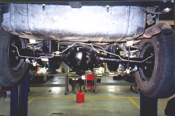
Once the driveshaft was in, I was able to determine what needed to be done with the pinion angle. After measuring the angles of the driveshaft and the pinion yoke, I decided to adjust the upper control arms to their minimum length of 13-1/8" and extend the lower arms to 16-3/8". This put the pinion at 13 degrees and the driveshaft at 13.5 degrees and completely eliminated the vibrations. The final step was to install the longer vent line and zip tie the brake line to the housing to make it more secure. I have yet to install the ARB air lines as I am trying to source a 90 degree fitting to allow the air line to follow along the length of the axle housing without putting any severe bends in the lines.
Overall, the rear axle install was very easy. The quality of the axle housing assembly, brackets, and control arms is outstanding. Whether or not you get axles from RE, I highly recommend their bracket kits...they are strong, well thought out, and allow retention of all factory or aftermarket suspension components.
